Mechanical Aspects of the Conversion
(i.e. How to do it)
There are 3 axis to contend with. I will reference to them as the mill axis (X,Y,Z).
I designed all the components on the 3D CAD, and machined them in couple of days. You will not need anything stronger than the aluminum, except for the axles.
I decided to use stepper motors to directly drive all the axis. This is the cleanest way of doing it, but most demanding of the motors. It will also give you the best performance. I also wanted to retain the manual capability, so all the motors are dual shafted, with the handle on the other end. By carefully measuring the torque on all axis, I sized-up the motors. Remember that the torque specified by the manufacturers is static torque. In real operation, you can expect about 50% of that, if you are lucky. Furthermore, you must have a safety factor: I decided on 2.5X factor. This will guarantee no missing steps, unless you really screw up. Bigger is not always better either. The motors I selected were as follows:
q X-Axis: 1030 in.oz. You need something strong to push and accelerate the heavy apron, and 60lbs vice.
q Y-Axis: 260 in.oz. Surprisingly light duty, but the Y-axis is very smooth on Smithy. I almost used another 1300 oz. motor, but as they are bigger, and I elected the front mount, I thought they would stick out too far. This works great.
q Z-axis: 1300 in. oz. Initially, I had another 260 oz. motor - and that worked fine for most things, but more was needed for plunging in metals with ½" and larger mills.
Remember that you will never be able to perfectly align motors to the screws, so using helical couplers is imperative, or your motors will die a fast death. The correct coupler must be able to handle more than the maximum static torque.
I had initially converted using the supplied
Acme 10 TPI screws. The slowest axis was the long, X-axis. It would
reliably run at 40 in/min, and would stall at 80 in/min. Backlash
made me change over to ball-screws. They are 5 TPI, cheap (~$75
each including pre-loaded screws). 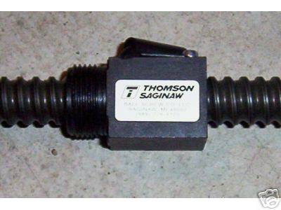 One
may expect that the speed would decrease even more due to 10 to 5
TPI switch. Not so: ball-screws are 95% efficient, while Acme is
closer to 35%. So, theoretically the motion speed should not
change, right? I was surprised to find my worst axis performing
like a champion. I was not able to lock it up at 180 in/min., which
was the maximum my PC would do. So, I set all the axes to 100
in/min, and now I know that 1% of my jog speed is 1 IPM (I often
use jog for manual cutting J ). The reason
for this performance increase (on both X and Y axes) is two
fold:
One
may expect that the speed would decrease even more due to 10 to 5
TPI switch. Not so: ball-screws are 95% efficient, while Acme is
closer to 35%. So, theoretically the motion speed should not
change, right? I was surprised to find my worst axis performing
like a champion. I was not able to lock it up at 180 in/min., which
was the maximum my PC would do. So, I set all the axes to 100
in/min, and now I know that 1% of my jog speed is 1 IPM (I often
use jog for manual cutting J ). The reason
for this performance increase (on both X and Y axes) is two
fold:
Ball-screw efficiency was to be expected. But I forgot that 5 TPI screw needs to turn only half as fast as 10 TPI to achieve the same speed. Increasing RPM drastically reduces available stepper motor torque: 100 IPM is 500 RPM on a 5 TPI screw (about what I would consider the upper safe limit). The same speed on 10 TPI screw is 1000RPM, which is beyond its capability, unless the load is very light.
My 200 step/rev motors are micro-stepped by Gecko Drives at 10X, thus I get have 2000 steps/rev. Thus, using 5 TPI screws, one step is 0.0001". Convenient, huh?
If going to ball-screws, remember that they are case hardened. You will have great trouble machining them. Instead, pay to have it done. It cost me $90 for both to have them finished. I got mine from http://www.homeshopcnc.com and they also did the machining for me. I only have nice things to say about them. Rick LaLonde was very helpful with answering implementation questions. They have switched from Thomson to Nook Industries screws: part# SBN10325. At the average load I am projecting, the life expectancy is in excess of 500,000 in. of travel. That is 1000 hours of continuous 10 IPM heavy load machining. In reality more like 10,000 hours of operation. The above screw picture is borrowed from their website.
Below are some pictures showing the implementation with associated comments. Everything should be self-explanatory (I hope).
X-Axis
.JPG)
.JPG)
.JPG)
.JPG)
.JPG)
.JPG)
Parts, and their assembly (click on the pics to see the larger version)
Note the six screws M5 fasteners holding the ball-screw flange. This many is needed due to 1000 lbs screw maximum pull force. Also, I tilted the X-motor mount at 45 degrees, and used it to mount my pendant. As it turned out, this was an ideal place.
Y-Axis
.JPG)
.JPG)
.JPG)
.JPG)
(click on the pics to see the larger version)
These pictures show the basic parts used for the conversion as well as the installation process. The front mount plate has roller bearings on both sides. They are rated at over 1000 lbs, and are crucial to eliminating backlash introduced due to screw axial play. Make sure to grease them very well.
.JPG)
.JPG)
.JPG)
.JPG)
(click on the pics to see the larger version)
The motor is held by a flange machined out of a solid chunk of aluminum. It houses the coupler, and is positioned so that the chips are kept out of the cavity.
.JPG)
.JPG)
.JPG)
(click on the pics to see the larger version)
The middle picture shows how the lead screw was originally coupled to the carriage. The yellow flange used to hold a gear used for driving the table. This is the location I chose to mount the ball nut. It is screwed into, and positioned by an aluminum flange to the right. As the CNC was completed before I switched to the ball-screws, I used it to make its own part. You can see the 15/16" - 16 TPI threaded section for anchoring. This was done by thread milling, using a ¾", 60 carbide degree cutter.
Z-Axis
.JPG)
.JPG)
.JPG)
.JPG)
Parts, and their assembly (click on the pics to see the larger version)
.JPG)
.JPG)
The above pictures show the Z-axis layout. Note that the bottom two pictures depict a different motor. This was after I switched to 1300 oz. model. It is held by a square profile aluminum section, which is also used to hold the mist unit.